Philips SM30 User Manual
Browse online or download User Manual for Audio amplifiers Philips SM30. Philips SM30 User's Manual
- Page / 72
- Table of contents
- BOOKMARKS
- Sound Management System 1
- ■ Zone Selection Indicator 4
- ■ 4 Function Keys 4
- ■ Alternative functions 4
- Fig. 1 - Block diagram 5
- Time signals 9
- * SM 30 SYSTEM * 11
- TUNER 1 87 11
- Fig. 4.3 12
- Fig. 4.2 12
- Fig. 5.1 13
- LBB 1282LBB 1283 LBB 1282 14
- LBB 1286 14
- LBB 1284 14
- LBB 1287 LBB 1288 14
- Fig. 5.2 - Top view 15
- PHIL IPS 16
- Fig. 6.1 - Call Station 21
- Fig. 6.2 - CST adjustments 22
- Fig. 7 - CSM 24
- Fig. 8 - MIM 25
- Fig. 9 - CIM 27
- LBB 1285 29
- Fig. 12.1 - ZRM 32
- Fig. 12.2 - Coupling zones 33
- LBB 1288 34
- Call Stations 38
- 3.12 Call routing to Zones 45
- See program step 1.13 45
- See program step 1.7 45
- 15 SM30 SYSTEM SPECIFICATION 46
- MUSIC ROUTING 49
- CONTENTS page 52
- 14.6 Setup programming 3 52
- 14.7 Installer programming 3 52
- POWER - ON - DELAY 56
- SELECT LANGUAGE 57
- STORE HARDWARE 57
- SELECT PROGRAM : 58
- BUSY STORING 58
- VOL STEP / REPEAT 59
- REPEAT MODE 59
- Override Relays 60
- ROUTING LIMITS 61
- SELECT ITEM 61
- CALL STATION : X 61
- CTL ALARM MODE 62
- F L EX. F UNCT. 1000 63
- Extended Call Station 64
- MUSIC INPUT TEXT 65
- AMPLIFIER CONFIG 65
- INSTALLER PASWORD 65
- GO TO SETUP 66
- XX0000 REL : 03 68
- PRIORITY : X 68
- SELECT ITEM : 69
- ENABLE REMOTE 69
- MUSIC MUTE : X 69
- Printed in the Netherlands 72
- 3922 988 33415 20/97 72
Summary of Contents
Philips Communication & Security SystemsSM30Sound Management SystemUser ManualLBB 1280User ManualGB/SM 30 user manual 5/26/98 10:17 AM Page 1
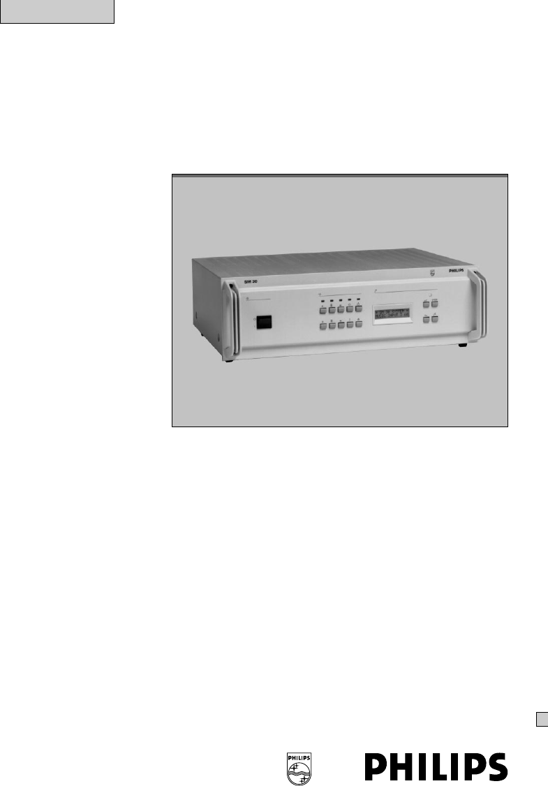
84 CONTROL CENTRE LBB 1280At the heart of each SM30 soundmanagement system is the Control Centre.This is a self contained unit, housing themicroproces
9Alpha-Numeric LCD Display (fig.4.1D)In the normal ‘Run’ mode of the system, theback-lit LCD display indicates the name ofthe current music source (e.g
104.2 SM30 basic modulesOn delivery the rear panel of the SM30Control Centre (fig.5.1) contains the LineOutput Module and the Power SupplyModule, as we
115. SETTING UP THE HARDWARE5.1 GeneralThe SM30 Control Centre is delivered withonly the Line Output Module (LOM) andthe Power Supply Module (PSM) mou
125.2 Opening the housingWARNING: Before attempting to openthe housing, the mains lead and the 48 VDC battery plug should be disconnected.It is not su
13The retaining bar (fig.5.2A) can now bereplaced by sliding it down in its slots as faras possible, and tightening the screws in itsends (fig.5.2B).5.3
145.4 Mounting in a 19” rackThe SM30 Control Centre is available intwo versions:LBB 1280/30 for table top use including thecover.LBB 1280/40 for 19” r
153 It is always preferable to mount poweramplifiers, which generate a certainamount of heat, above heat sensitiveequipment, like SM30.If however, powe
161313CCSQ45SM304XFig. 5.5.1 - Two channel systemGB/SM 30 user manual 5/26/98 10:18 AM Page 16
17113CSQ45SM30Fig. 5.5.2 - One channel systemGB/SM 30 user manual 5/26/98 10:18 AM Page 17
CONTENTS page1 Introduction 12 System operation 43 Attention and alarm signals 64 Control centre LBB 1280 85 Setting up the hardware 116 SM30 call sta
6 CALL STATION(CST) LBB 9568The SM30 Call Station presents theoperator with a logical, comprehensive, andeasy to use method of routing andbroadcasting
19NOTE: If a Function Key and the Keypadare both selected to activate a call, the lastselection will always have precedence,cancelling any other selec
206.2 InstallationLoudspeaker Zone TemplateA paper template is provided, on which thenames of the loudspeaker zones can bewritten. The template has a
211-, then 5. As stated earlier, the ZoneRouting Indicator LEDs for these zoneswill be illuminated.2 If the red ‘BUSY’ LED is flashing, thismeans that
227 CALL STATION INPUT MODULE(CSM) LBB 1283Each Call Station Input Module allows twoSM30 Call Stations to be connected to theControl Centre. SM30 will
238 MICROPHONE INPUT MODULE(MIM) LBB 1282Each Microphone Input Module allows twoelectret microphones or two dynamicmicrophones to be connected to the
24Connection of MicrophonesThe design of SM30 allows a single cable tobe used to connect a Microphone to one ofthe sockets of the Microphone InputModu
25remote equipment, activatesignalling/warning lamps, etc..Input 1-8Apart from the normal functions,inputs 1-8 can be programmed todistribute an exter
2610 RECORDED MESSAGE MODULE(RMM) LBB 1285A unique feature of SM30 is its RecordedMessage Module, which allows up to 4individual messages to be record
27numerical order, commencing with message1.Recording a Message To record the first message, slide theMessage Selection switch to position ‘1’. Next
11 INTRODUCTIONThe SM30 sound management systemprovides an ideal solution for public addressdistribution systems, requiring a compactand flexible set-u
28The Function switch must be in its lowest(system) position for messages to be replayedthrough the system.When the Function switch is in its top(reco
29Output Treble and Bass Tone ControlsTreble and Bass potentiometers (fig.11C andD) provide tone control facilities for theoutput of the module.In the
3012 ZONE RELAY MODULE(ZRM) LBB 1287The SM30 system is intended for use with 2separate amplifiers, or two separate channelsof a multi channel amplifier.
3112.2 Coupling Zone Relay ModulesWhen more than 1 Zone Relay Module isused in a system, the inputs of the modulesmay be linked together (fig.12.2), so
3213 CONTROL RELAY MODULE(CRM) LBB 1288The Control Relay module provides SM30with a set of switching contacts, which canbe opened or closed (dependent
33Microphone Input module should be startedwith contact 1-8 of the Control InputModule. See user programming 14.3 menuitem 3.8 ‘Control inputs 1-8’.Re
3414 PROGRAMMING14.1 Summary SM30 User Programmingprogram step selectionUser password 0 1.1 CALL STATIONS1.2 - number 1-2, 3-4, 5-61.3 - Keypad 0-6, 7
3514.2 Introduction14.2.1 GeneralProgramming is carried out using the keyson the front panel of SM30 Control Centre.A password must be keyed in via th
36Call StationsSELECT PROGRAM :CALL STATIONSSELECT ITEM :CALL STATION : XSELECT FUNCTION :FUNCTION KEY : F1 - 4SELECT FUNCTION :KEY PADCALLST : X FK
3714.3 User Programming14.3.1 CALL STATIONS1.1 Main menu selectionSelect from the main menu by means of theleft/right arrow keys:CALL STATIONS1.2 Call
2SM30 plug-in modulesAll of the interconnections betweenindividual modules in the Control Centretake place automatically when they areplugged into the
38Relay 1 (marked ‘X’) is reserved for theactivation of error indicators, if a processorfailure is detected, and cannot beprogrammed for any other fun
39also be programmed with one of six morefunctions. The ‘music’ functions are onlyavailable if the Music Input Module ispresent.The ‘relays’ functions
402 MICROPHONES2.1 Main menu selectionSelect from the main menu by means of theleft/right arrow keys:MICROPHONES.2.2 Microphone number selectionPressi
412.7 Programming Control RelaysThis display will be skipped if the ControlRelay Module is not present in the system.The current setting of Control re
4214.3.3 CONTROL INPUTS3.1 Main menu selectionSelect from the main menu by means of theleft/right arrow keys: CONTROL INPUTS.3.2 Control input number
433.12 Call routing to ZonesSee program step 1.13.3.13 Programming Control RelaysSee program step 1.7.Control InputsSELECT PROGRAM :CONTROL INPUTSSELE
4415 SM30 SYSTEM SPECIFICATIONGENERALThe specification relates to a Control Centre with corresponding modules.MICROPROCESSOR HARDWARE- EEPROM data stor
45Click suppression in combination for any module- for audio switching : > 60 dB- for power on/off switching : > 30 dB- mute by on/off switch :
46Audio signal level diagram201141049484746454443424141040-10-30-40-60-70-80-90-110-120dB10V100mV10mV1mV124134CST CSM CALLMIM MUMSM30MUSICCONTROLCENTR
4714.3.4 MUSIC ROUTING4.1 Main menu selectionSelect from the main menu by means of theleft/right arrow keys:MUSIC ROUTING.4.2 Zone selectionThe curren
3Zone relaymodulemoduleZone relaymoduleZone relayControl relaymodulePowersupplyDispl/keyboardLine output moduleMusic inputMicrophoneCall stationContro
48GB/SM 30 user manual 5/26/98 10:18 AM Page 48
Philips Communication & Security SystemsSM30Sound Management SystemSupplementInstructions for installationLBB 1280GB/SM 30 user manual 5/26/98 10
CONTENTS page14.5 Summary SM 30 installer programming 114.6 Setup programming 314.7 Installer programming 3GB/SM 30 user manual 5/26/98 10:18 AM Pag
114.5 Summary SM30 Installer ProgrammingSetup programming steps selection5.0 Installer password | 7.1 LANGUAGE SELECT8.1 STORE HARDWARE1.1 CALL STATIO
2SetupSETUP PROGRAMMINGMAINS "ON""RUN-MODE"EMPTY MEMORYWITH / WITHOUTMUM INSTALLEDFACTORY SETTING/SYSTEM IS DOWN* SM30 SYSTEM ***
314.6 SETUP PROGRAMMINGIf the memory is clear, the software must beable to recognise the hardware that isinstalled before programming can beundertaken
414.7.5 POWER-ON DELAYThis program is intended for batteryoperated systems where, in order to conservebattery power, the amplifier is switched ononly w
514.7.6 ALTERNATIVE MUSIC INPUTTEXTIf the music input module is present, thesecond line of the display shows in thenormal RUN mode the currently selec
614.7.8 STORING HARDWARECONFIGURATIONTo enable the system to check that allmodules are communicating with theprocessor, the hardware configuration has
714.7.10 REMOTE VOLUME CONTROLMUSICThis program effects the operation of themusic volume control, which is activated viathe Call Station Function Keys
42 SYSTEM OPERATIONSM30 Sound Management System presentsthe operator with a logical, comprehensive,and easy to use method of routing andbroadcasting c
814.7.11 VOLUME CONTROLOVERRIDE RELAYSWith this function one or more ControlRelays (1-12) can be coupled to Zone Relays(1-6, 7-12, 13-18) for volume o
913 DIRECT ROUTINGThis program is used to directly activate theZone Relay Module(s) e.g. via an externalfire detection system.Control inputs 1-6, 1-12
1014.7.14 CLEARING MEMORY14.1 Main menu selectionSelect from the main menu by means of theleft/right arrow keys: CLEAR MEMORY14.2 ConfirmationSince thi
1115.2 Current mode displayThe display will show the current mode.15.3 Mode selectionSelection of the non-interruptable orinterruptable mode can be ma
1214.7.17 EXTENDED CALL STATIONPROGRAMMINGThe SM30 system with more than 18loudspeaker zones needs one Module FrameLBB 1291/40 and eventually one or m
13MUSIC INPUT TEXTSELECT TEXT OFMUSIC INPUT : XSCROLL WITHXXXXXXSELECT PROGRAM :1236SELECT PROGRAM :POWER - ON - DELAYPOWER - ON - DELAYENTER SECONDS
14SELECT PROGRAM :VOL STEP / REPEATVOLUME CONTROLSTEP MODEVOLUME CONTROLREPEAT MODE12310SELECT PROGRAM :OVERRIDE RELAYSSELECT ZONE : XXSELECT ZONE : X
15SELECT PROGRAM :CTL ALARM MODENON - INTERRUPTINTERRUPTABLE12315SELECT PROGRAM :FLEXIBLE KEYSSELECT ITEMCST X FKEYS: 123423116SELECT PROGRAM :EXTENDE
16SELECT PROGRAM :CALL STATIONSSELECT ITEM :CALL STATION : XSELECT FUNCTION :FUNCTION KEY : F1 - 4SELECT FUNCTION :KEY PADCALLST : X FKEY : XCALLST
171233 8SELECT PROGRAM :CONTROL INPUTSSELECT ITEM :CONTROL INPUT : XX1ENABLE REMOTEMUSIC VOLUME: XPRIORITY : X1 - 8CONTROL INPUT : XX9 - 1718-24476591
5Volume Control Override RelaysIt is important that announcements and/oralarm signals come through at full volume,regardless of the volume settings of
GB/SM 30 user manual 5/26/98 10:18 AM Page 18
GB/SM 30 user manual 5/26/98 10:18 AM Page 19
Data subject to changes without noticePrinted in the Netherlands3922 988 33415 20/97GB/SM 30 user manual 5/26/98 10:18 AM Page 20
6Station) details the way in which each typeof call, when activated via the Call Station,can be terminated.Signal descriptionSignal numbers from 1 up
730 Alternating signal, frequencies of 650 and850 Hz, every frequency lasts 500 msec.Signal duration 60 seconds.31 As signal 30, lasts until second ac
Related products and manuals for Audio amplifiers Philips SM30
 (20 pages)
 (2 pages)
© 2020, manymanuals.com. All rights reserved. | 0.591 s |
 Manymanuals.com
 Manymanuals.de
 Manymanuals.fr
 Manymanuals.it
 Manymanuals.pl
 Manymanuals.cz
 Manymanuals.es
 Manymanuals-pt.com
Comments to this Manuals